In today’s steel manufacturing sector, automation is no longer a luxury but a necessity to stay competitive. Integrating pneumatic clamps controlled via PLCs forms the backbone of a smarter and more reliable hot rolling production line. Whether you are an engineer or a technical manager, this guide walks you through the core steps of setting up interfaces, designing control logic, and ensuring safe, seamless operation across robotic or AGV systems. Let’s unlock the potential to make your hot rolling line faster, steadier, and smarter.
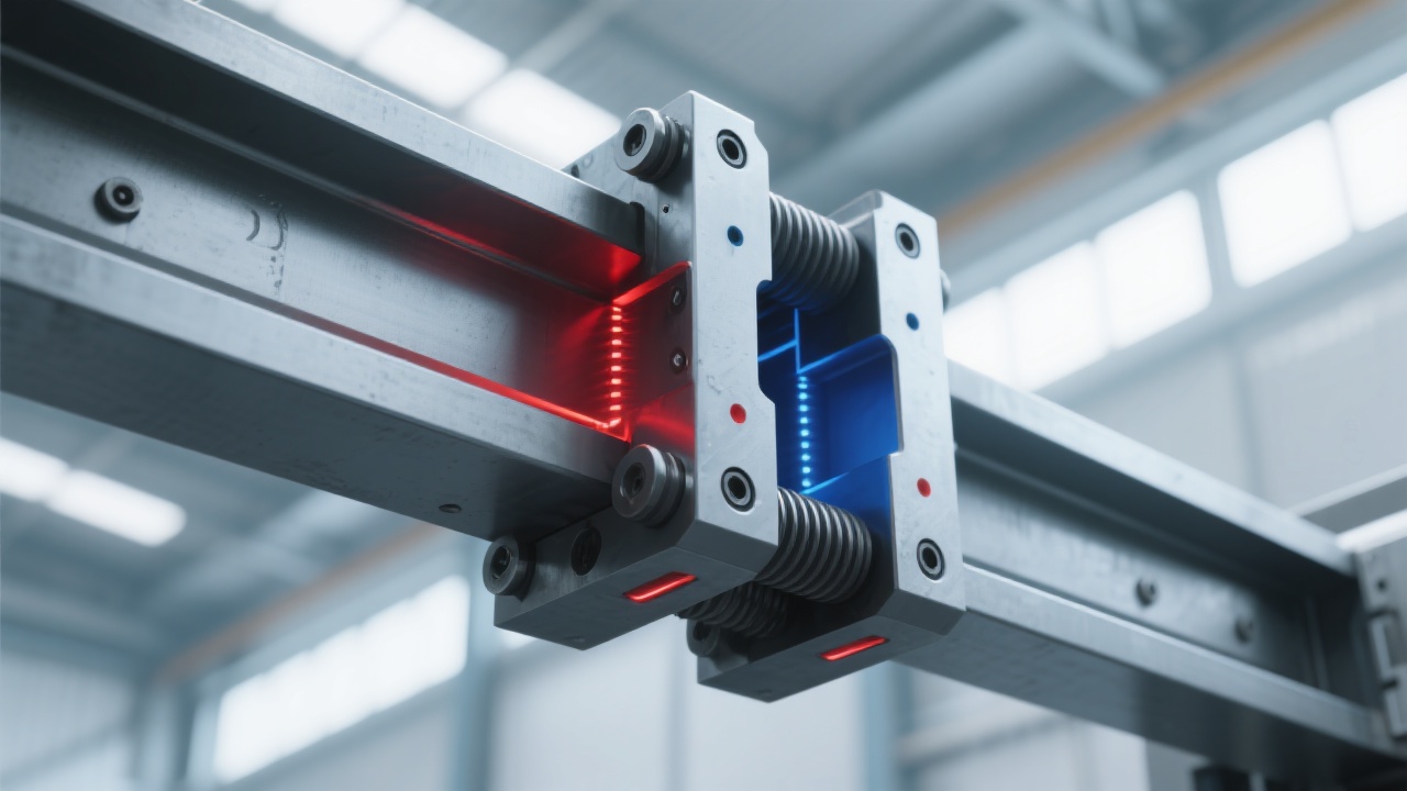
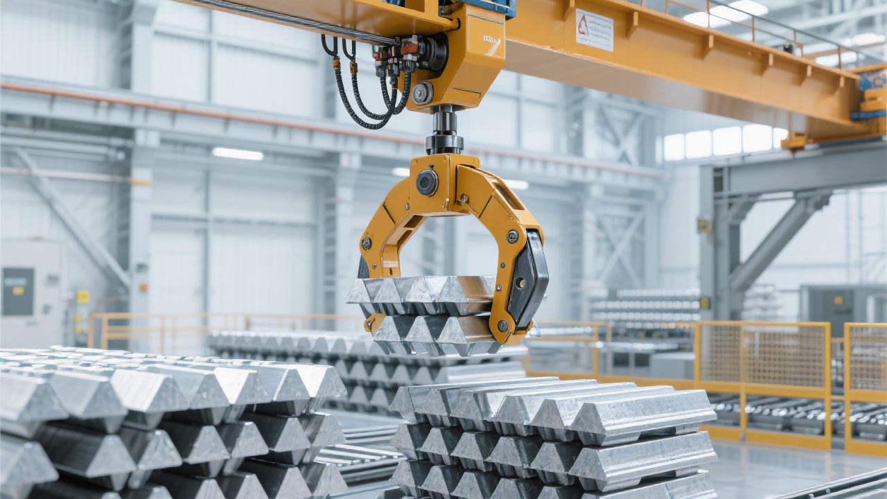
Pneumatic clamps are critical to securing high-temperature steel plates during processing and transportation. Automated integration enables:
Leading industry studies show automation can improve throughput efficiency by up to 25% and reduce downtime by approximately 18%.
Let’s delve into the physical and communication aspects vital to reliable integration.
| Interface Component | Function | Configuration Tips |
|---|---|---|
| Digital Input/Output (I/O) Terminals | Signals for clamp open/close commands and feedback | Use shielded cables and isolate high-voltage lines to prevent noise |
| Pneumatic Solenoid Valves | Control compressed air flow for clamp operation | Calibrate air pressure between 0.5 to 0.7 MPa for stable actuation |
| Communication Protocols (e.g., Modbus, PROFIBUS) | Real-time data exchange for status monitoring | Ensure protocol compatibility and implement error-checking mechanisms |
The correct timing and safety of pneumatic clamp actions critically impact production integrity. Below is a typical workflow logic:
Safety Interlock Essentials: Emergency stops, dual feedback from limit switches, pressure sensors, and logic checks prevent accidental clamp movements, protecting personnel and equipment.
// Example Ladder Logic Snippet (Simplified)
---[ Start Button ]-------------( SET Clamping )
---[ Clamping Done ]------------( ENABLE Movement )
---[ Emergency Stop ]---------( RESET Clamping & Movement )
Leading customers in the steel industry report that tailored PLC-pneumatic clamp setups yield:
Implementing TiDing Heavy Industry’s core technology for interface and logic design can dramatically accelerate your automation upgrade.
When setting up your system, pay close attention to:
| Check Point | Recommended Standard |
|---|---|
| Pneumatic Air Pressure | Maintain 0.6 MPa ± 0.05 MPa for stable clamp cycles |
| Limit Switch Calibration | Set activation points with ±1 mm accuracy to avoid false signals |
| Anti-Vibration Measures | Use vibration dampeners and delay timers to reduce signal chatter |
Check pneumatic pressure level and solenoid valve responsiveness. Also verify limit switch alignment and wiring integrity.
Implement signal debouncing timers and ensure proper shielding of I/O cables from electromagnetic interference.
Yes, provided the PLC communication protocols match. Many systems support Modbus or PROFIBUS for seamless data exchange.

Embark on the next step toward intelligent hot rolling automation. Discover How TiDing Heavy Industry’s Core Technologies Can Empower Your Production Line