Implementing Safe Interlock Mechanisms Between Robotic Handling Systems and Automated Grippers: Key Technologies Explained
26 07,2025
Technical knowledge
Ensuring seamless and safe integration of robotic handling systems with pneumatic grippers in hot rolling production lines is critical for advancing smart manufacturing in the steel industry. This article thoroughly explores the essential technical aspects of interlocking automation grippers with PLCs, robots, and AGVs, including signal interface configuration, action sequence programming, and multi-layered safety interlock principles. Practical insights on pneumatic drive coordination, input/output signal mapping, delay protection, and synchronized gripping-motion control are shared to address common operational challenges. Complemented by real-world project examples and commissioning tips such as air pressure calibration and debounce techniques for limit switches, this guide empowers engineers to build highly reliable automated handling systems that enhance safety and efficiency on the shop floor.

Mastering Safety Interlock Mechanisms for Robot Handling Systems with Automated Clamps in Hot Rolling Lines
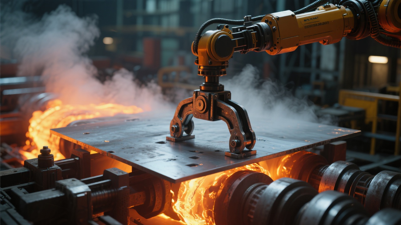
In the steel industry, especially within hot rolling production lines, seamless integration of robotic handling systems with automated pneumatic clamps is crucial to achieving high-efficiency and safe operations. However, many engineers struggle with ensuring robust safety interlocks that synchronize clamp actions with robot or AGV motions, avoiding costly downtime and accidents. This article breaks down the technical essentials of implementing reliable safety interlock systems between pneumatic clamps and PLC-controlled robots, supported by real-life cases and field-tested advice. The insights shared will equip automation professionals to help steel enterprises advance toward smart manufacturing – making every grip safer, quicker, and more consistent.
Understanding the Integration Flow of Automated Clamps in Hot Rolling Lines
Before diving into safety logic, it’s essential to outline the typical integration process of pneumatic clamps within a hot rolling environment:
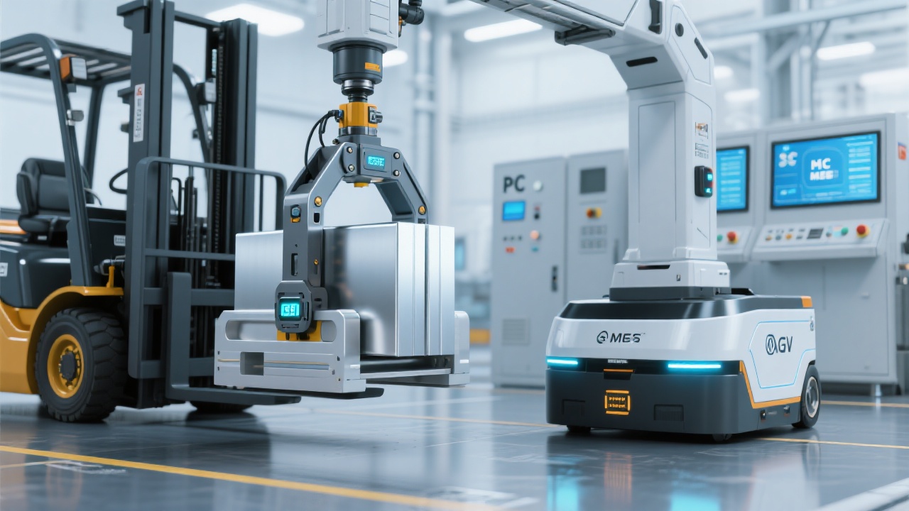
- Define clamp actuation roles aligned with robotics or AGV pick-and-place tasks.
- Establish physical and logical connections between the pneumatic subsystem, PLC, and robot controllers.
- Design safety interlocks that prevent clamp engagement/disengagement during unsafe robot movements.
- Test sequences on-site to ensure synchrony between clamp state feedback and mechanical arm positioning.
Skipping or simplifying any of these steps often leads to operational hazards such as unintended clamp openings under load or robot-activated collisions.
Key Technical Points: Pneumatic Clamp and PLC Signal Interface Matching
The PLC acts as the brain interface, orchestrating clamp commands with robotic maneuvers. Proper signal mapping and timing parameters are vital:
| Signal Type |
Description |
Function & Comments |
| Digital Output (DO) |
Command signal from PLC to pneumatic valve |
Triggers clamp open/close actions; requires debounce and fail-safe overrides |
| Digital Input (DI) |
Feedback from clamp limit switches |
Confirms clamp position; used in interlocking logic for robot motion authorization |
| Analog Input (AI) |
Pressure sensor signals |
Verifies pneumatic pressure within safe range before clamp actuation |
A critical detail is interlock delay timing. Typically, a delay of 200–500 milliseconds is programmed post-command to allow clamp mechanical action completion before robot movement resumes. This prevents premature arm movement causing clamp slippage or product damage.
Synchronizing Clamp and Robot Motion: Coordinated Control Strategies
The operational harmony between the clamp’s gripping sequence and the robot’s trajectory is governed by coordinated control logic, usually managed inside the PLC program or robot controller.
The standard flow includes:
- Robot moves to approaching position without load, signaling “ready to grip.”
- PLC energizes clamp DO to close the jaw; DI inputs from limit switches verify clamp fully closed.
- Once clamp closed signal is confirmed, robot initiates lifting and transport movement.
- During transport, continuous monitoring of pressure AI and mechanical feedback informs safety overrides.
- At destination, robot signals “ready to release,” PLC opens clamp and verifies open status before robot retracts.
This sequenced interaction is often augmented with safety relays or watchdog timers, enhancing the fault detection and isolation mechanisms.
Pro Tip: Clamp Limit Switch Debounce and Noise Filtering
Due to mechanical vibrations and electromagnetic interference typical in steel plants, limit switch signals frequently experience "bouncing" or noise. Adding debounce time (typically 50-100 ms) in PLC logic prevents false position readings, reducing unexpected stoppages.
Field-Proven Installation & Commissioning Tips
Practical experience reveals key setup pointers for maximizing system reliability:
- Air Pressure Calibration: Maintain pneumatic pressure consistently between 5.5 and 6.0 bar; pressure fluctuations beyond ±0.2 bar degrade clamp force, risking load slips.
- Limit Switch Placement: Adjust switches precisely to physically detect clamp jaws’ extreme positions; misplacements cause false feedback.
- Exception Feedback: Integrate diagnostic signals for anomalies such as stuck clamps or air leaks to PLC alarms to enable prompt operator response.
- Redundant Safety Layers: Install hardware e-stops and interlock relays to immediately halt robot movement in emergency states.
Real-World Success: Steel Plant Robotic Clamp Integration Case Study
Client: Leading European hot rolling steel producer
Challenge: Legacy clamp system lacked interlocked communication, causing frequent downtime and safety incidents.
Solution: We designed a PLC-controlled pneumatic clamp interface with verified limit switch feedback and incorporated robot motion permissive signals.
Outcome: Clamp-related stoppages reduced from 12 per month to under 2; overall line throughput rose by 8%. Safety incidents related to clamp misoperation were completely eliminated over 18 months.
Frequently Asked Questions (FAQs)
-
Q: What is the typical response time for safety interlock confirmation?
-
Standard interlock confirmation including signal debounce and mechanical actuation delays ranges between 200 to 500 milliseconds depending on system specifications.
-
Q: How to ensure safety in abrupt power loss scenarios?
-
Implement hardware fail-safe valves that default clamp jaws to a safe position (usually open) upon power or air supply loss, combined with emergency stop safety circuits.
-
Q: Can the clamp control be integrated with different brands of PLC or robot controllers?
-
Yes, the key is to conform to standard IO signals and define clear communication protocols. Most mainstream PLCs and robot controllers support such customized integration.
Take Your Steel Production Line to the Next Level of Automation and Safety
Combining pneumatic clamp systems with robotic handling offers huge potential to boost productivity—but only when safety interlocks and signal synchronization are carefully engineered and field-proven.
Discover Proven Safety Interlock Solutions Tailored for Your Hot Rolling Line
Have you encountered challenges synchronizing robotic clamps in your automated steel processes? Share your scenario with us, and we’ll provide customized case studies and practical solutions from global steel industry experts.

%20Clamp-1.jpg?x-oss-process=image/resize,m_fill,h_600,w_600/format,webp)