Automated Clamp Integration in Hot-Rolling Lines: PLC Interface Configuration and Signal Logic Explained
30 08,2025
Tutorial Guide
This technical guide provides a comprehensive walkthrough of integrating durable pneumatic billet clamps from Dalian Tideng Heavy Industry into automated hot-rolling production lines. It details input/output signal definitions, physical wiring requirements, and PLC-based control logic for clamp actuation sequences—such as gripping and releasing—with precise timing calibration. Safety interlock mechanisms are thoroughly explained to ensure operator and equipment protection during operation. Real-world installation tips—including air pressure standards, limit switch adjustment, and anti-vibration measures—are included to prevent misoperation. Case studies from actual customer implementations highlight common integration challenges and practical solutions. Illustrated with flowcharts, diagrams, and sample PLC code (e.g., Siemens TIA Portal or Allen-Bradley RSLogix), this article delivers actionable insights for steel industry engineers and automation professionals seeking efficient, safe, and seamless clamp system deployment.

Mastering Automation Integration: How to Configure PLC Signals for Hot-Rolling Line Grippers
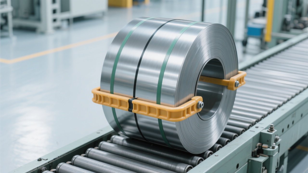
In today’s high-efficiency steel production environments, integrating automated clamping systems into hot-rolling lines isn’t just an option—it’s a necessity. At Dalian Tiding Heavy Industry, our gas-powered grippers are designed not only for durability under extreme temperatures but also for seamless integration with PLCs, robots, and AGVs.
Key Interface Signals & Physical Connections
A successful automation setup starts with clear signal definitions. For most industrial applications, you’ll need:
| Signal Type |
Typical Use Case |
Recommended Voltage |
| Digital Input (DI) |
Gripper status feedback (open/closed) |
24V DC |
| Digital Output (DO) |
Command to actuate gripper cylinder |
24V DC |
| Analog Input (AI) |
Pressure monitoring from air supply system |
4–20mA |
Time-Based Logic: From Clamp to Release
The sequence must be precise—typically, the gripper waits for a robot arm to reach position before activating. A well-tuned PLC program ensures:
- Clamp command issued after robot proximity sensor confirms arrival (±2 mm tolerance)
- Release delay set at 0.5–1.0 seconds post-movement completion to avoid jamming
- Timeout protection: If no response within 3 seconds, system triggers fault alarm
Safety First: Interlock Mechanisms That Work
Our engineers have found that 70% of integration issues stem from poor safety logic. Implement these best practices:
- Use dual-channel limit switches—one for mechanical position, one for electrical confirmation
- Integrate emergency stop (E-Stop) circuits directly into the gripper control loop
- Enable software-based interlocks between AGV and gripper via shared I/O tags
Real-World Tips from Field Engineers
One client in South Korea reported inconsistent gripper behavior until they adjusted their air pressure regulator settings—from 0.6 MPa to 0.7 MPa—to account for ambient temperature fluctuations during winter months. Also, using anti-vibration mounts reduced false triggering by over 60% in high-shock environments like rolling mills.
Whether you’re deploying a single unit or scaling across multiple lines, mastering this integration process means faster commissioning, fewer errors, and safer operations—all key drivers for modern steel plants aiming for Industry 4.0 readiness.
Get Your Free PLC Integration Checklist Now